What Level of Simulation Do You Really Need?

If you're developing control system software today, you have no shortage of ways to simulate and test it. You can write unit tests, build a higher-level engineering model, run an application in a simulated controller environment, model the physics of a machine, place that machine in a virtual environment, emulate an embedded target, connect a real controller to HIL, or test on the machine itself.
All of these approaches can be useful. The more interesting question is not which simulator is the most capable, but:
What are you actually trying to understand?
That question matters because simulation is not only about how much of the system we reproduce. It is also about the abstraction at which we choose to represent the problem. A unit test may be enough to verify a calculation. A higher-level model may be the right place to design a control concept. A physical model may be necessary when hydraulics or mechanics dominate the behavior. And sometimes the production implementation already contains the behavior we need to investigate.
The table below is not a ranking, and the products listed are not necessarily direct competitors. It is a map of different starting points and the kinds of questions they help answer.
| Approach | Examples | What it helps you understand |
|---|---|---|
| Unit testing | GoogleTest, Catch2 | Individual calculations, conditions and module behavior |
| Code-first control system simulation | CppModel | How the production implementation behaves over time |
| PLC engineering & simulation | CODESYS, Beckhoff TwinCAT, Siemens PLCSIM | Running, debugging and observing controller applications in a simulated controller environment |
| Model-Based Design | Simulink, SCADE | Control design and behavior represented at a higher modeling abstraction, including model-based development and code-generation workflows |
| Physical/system modeling | Simscape, OpenModelica | Interaction between control and physical processes |
| Robotics/environment simulation | Gazebo, Webots, CoppeliaSim | Motion, sensors, physics and interaction with a virtual environment |
| Embedded platform simulation/emulation | Renode, QEMU | Firmware behavior in relation to processors, memory and peripherals |
| Distributed ECU/network simulation | Vector CANoe | Communication, interfaces and interaction between ECUs |
| Hardware-in-the-loop | HIL platforms | Real controller hardware interacting with a simulated process |
| Real-machine testing | The machine itself | Actual machine and process behavior |
The part of this landscape I want to focus on here is control system software and the behavior it creates in processes, machines and mechanisms.
CppModel starts from a deliberately simple premise: the code is the model. Instead of first creating a separate representation of the control system, it works directly with the production implementation—which in embedded and machine control is often C or C++—and observes its behavior over time. CppModel currently supports this approach for production C and C++ code.
This does not mean that the production implementation is always the only model we need. It means that when the behavior we are interested in is already expressed there, we can start there rather than first rebuilding the same logic at another abstraction level.
From Code to Behavior
Consider a simple velocity ramp. A machine receives a desired velocity, but we don't want the value sent toward the actuator to jump immediately to the requested value. Instead, we limit how quickly the current value can move toward the target.
The core logic can be remarkably small:
static float RampStep(float current, float target, float maxDelta)
{
    float delta = target - current;
    if (delta > maxDelta)
    {
        return current + maxDelta;
    }
    if (delta < -maxDelta)
    {
        return current - maxDelta;
    }
    return target;
}
There is deliberately nothing CppModel-specific in this function. It is intentionally minimal so the behavior is easy to follow. Production embedded code may use explicit project types, diagnostics, additional checks, saturation handling, and project-specific coding rules such as MISRA C.
Reading the function tells us what happens during one call. What it doesn't immediately show is what happens after hundreds of calls while the requested velocity changes. To see that, let's give it a simple velocity schedule:
static const VelocityLevel_ts VELOCITY_SCHEDULE[] = {
    {0,   50.0f},
    {300, 150.0f},
    {600, 30.0f},
    {900, 0.0f},
};
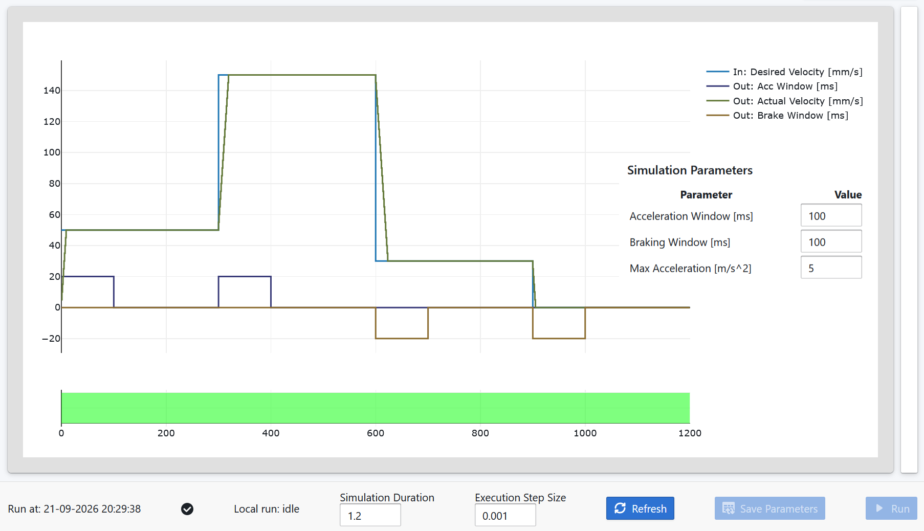
The requested velocity starts at 50, steps to 150 after 300 ms, drops to 30 after 600 ms, and finally goes to zero after 900 ms. In a short experiment we get acceleration from standstill, another acceleration step, a large deceleration, and braking to zero.
The experiment has three parameters:
| Parameter | Purpose |
|---|---|
MaxAcceleration | Limits how aggressively the velocity can change |
AccelerationWindowTimeMs | Defines the allowed acceleration window duration |
BrakingWindowTimeMs | Defines the allowed braking window duration |
For the runs below, both window times are set to 100 ms. The simulation runs for 1.2 seconds with an execution step of 1 ms.
This is the transition from code to behavior that matters here. The function calculates one control step. Execute it every millisecond through a defined scenario and those individual steps become a time-domain response that we can inspect and validate.
Now keep the code, input schedule, execution step and window times identical and change only MaxAcceleration.
With MaxAcceleration = 5, the controller follows the requested velocity quickly enough to satisfy the configured timing requirements:
Reduce MaxAcceleration to 2 and the shape of the response changes. The ramps take longer, but the configured requirements are still satisfied:
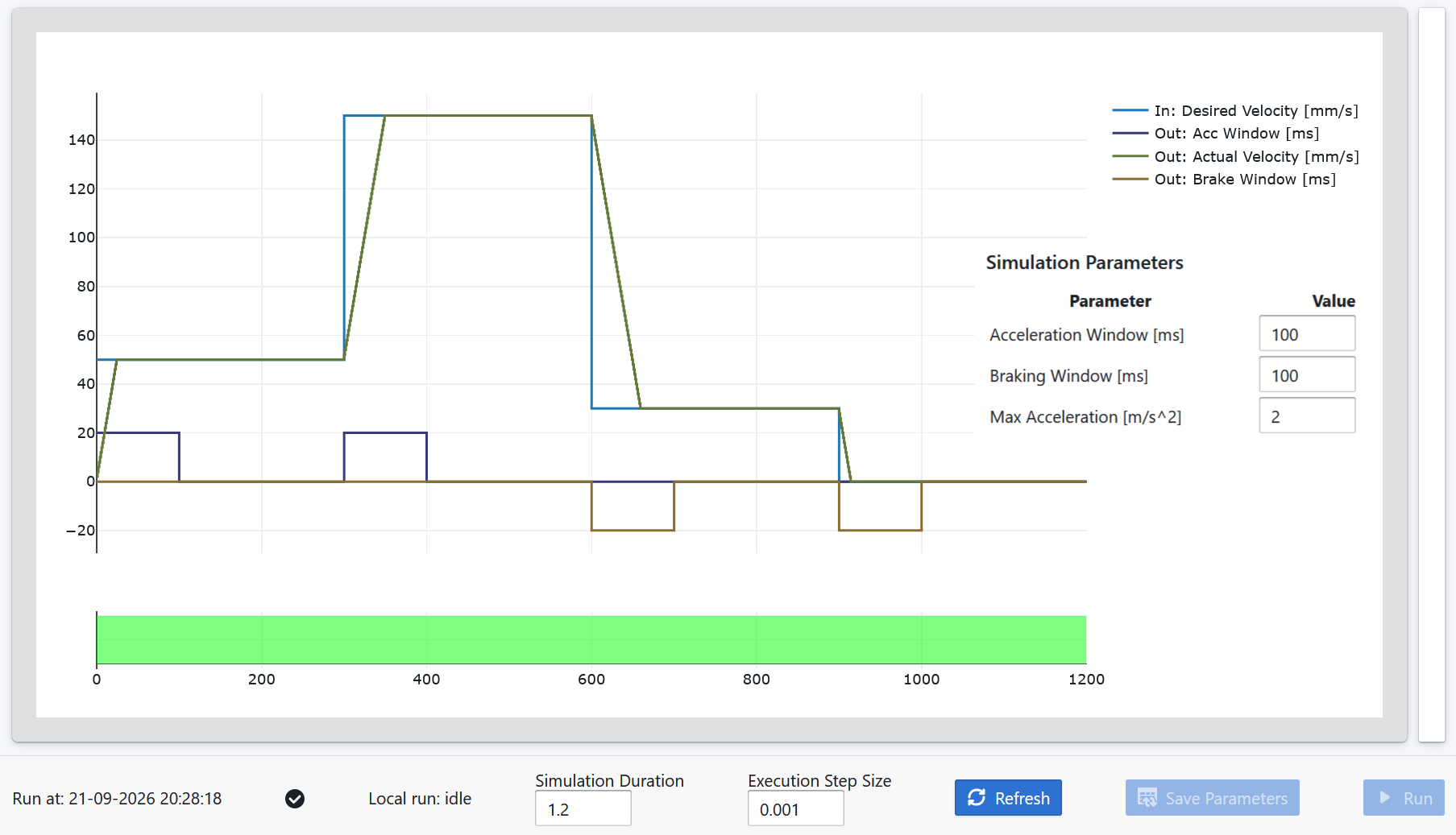
Both simulations pass, yet they clearly do not behave in the same way. That is an important distinction. A parameter tells us what we configured; the graph shows us what that configuration means for behavior over time.
On a real control system, the same idea extends beyond a simple ramp. We may be interested in filtering, settling, overshoot, oscillation, sequencing, state transitions, or the interaction between several pieces of logic. These are all things that can be difficult to understand from isolated function calls or individual values.
Now reduce MaxAcceleration once more, this time to 1.
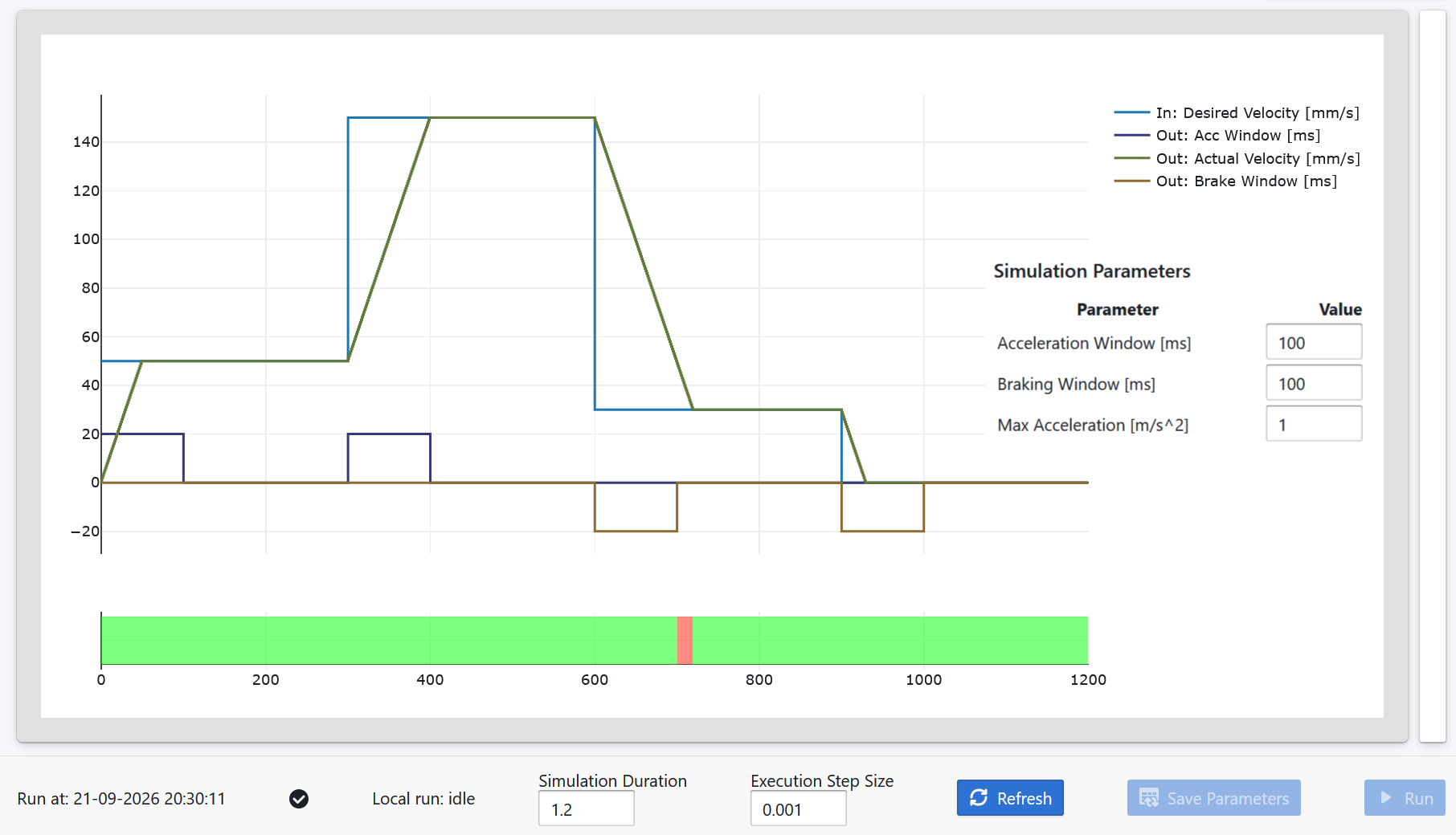
This time the validation fails. At the 600 ms transition, the desired velocity drops from 150 to 30. With the lower acceleration limit, the actual velocity cannot reach the new target within the configured 100 ms braking window. The failed region is visible alongside the response that produced it.
This is where simulation and testing start to complement each other. The test answers:
Did the behavior satisfy the requirement?
The graph helps answer:
Why didn't it?
That becomes particularly useful in continuous integration. The same scenario can be executed after a change and the requirements checked automatically, but the result does not have to stop at pass or fail. The behavior that produced the result can be preserved as evidence.
The earlier runs show the other side of the same idea. MaxAcceleration = 5 and MaxAcceleration = 2 both pass, while their responses are visibly different. Tests tell us whether the behavior satisfies the requirements we thought to encode. Looking at the behavior can also expose differences we never thought to express as assertions.
For control system software, where important behavior develops over time, that context can be as useful as the final test result.
The function gives us one step. The simulation gives us the behavior. The test tells us whether that behavior meets the requirements.
Where the Model Lives
The example above treats the production implementation itself as the model. That is one possible abstraction, but it is not the only one. The same control system can be represented at a higher level, surrounded by a model of the physical process, or eventually exercised together with real hardware.
This is where the distinction between code-first simulation and Model-Based Design becomes important.
CppModel is built around a model too. The difference is where that model lives and at what abstraction level.
In a Model-Based Design environment such as Simulink, the engineering model typically exists at a higher abstraction level. Control behavior can be described using blocks, signals, state machines and other modeling constructs. That representation can be simulated and validated and, depending on the workflow, used to generate production code.
That is a powerful approach when the engineering model itself is intended to be a primary design artifact.
CppModel starts from the other direction. When the control system behavior is already expressed in the production implementation, that implementation becomes the executable model. Simulation, visualization and validation are built around it rather than around a separate representation of the same algorithm.
Neither abstraction is inherently the right one. They answer somewhat different development needs. If you want to design and reason about the control system through a higher-level engineering representation, Model-Based Design may be the natural starting point. If the production implementation is the artifact you want to develop, observe and validate, working directly with that implementation can be more direct.
PLC engineering environments add another variation. Tools such as CODESYS provide simulation and debugging workflows that are often centered on running the controller application and observing or modifying it much as an engineer would with a live controller. The approach discussed here has a different emphasis: execute a defined scenario over a defined time interval, preserve the resulting behavior, validate it, and make the experiment repeatable in CI.
That distinction is not fundamentally C/C++ versus IEC 61131-3. It is also about how the control system implementation is exercised and how its behavior becomes part of the development and verification workflow. CppModel currently supports C and C++, but the idea of treating the production implementation as the model is not tied to those languages.
When the Model Needs to Grow
There is, of course, a limit to what the production implementation can tell us by itself.
Suppose the question is no longer whether the velocity algorithm reaches its target within 100 ms, but how a hydraulic cylinder, flexible structure, or loaded crane actually responds to that command. The missing behavior now lives in the physical system. Hydraulics, mechanics, electrical systems, loads, and other dynamics have to become part of the model. This is where tools such as Simscape or Modelica-based environments such as OpenModelica become appropriate.
The model may need to grow in another direction as well. If we want to understand how a controlled machine interacts with its environment—its motion, sensors, collisions, geometry, or surroundings—we need to represent that environment too. Robotics simulation environments such as Gazebo can provide this context, often as part of a ROS-based development workflow. At that point the question is no longer only what the control system implementation does over time, but what happens when that behavior is placed inside a simulated machine and environment.
Eventually, some questions depend on the real controller. When the behavior depends on the actual controller hardware, its I/O and electrical interfaces, or sufficiently realistic machine dynamics, HIL can bring the real controller into the experiment. And some behavior can only be established with confidence on the real machine.
Other tools extend the engineering context in different directions rather than simply making the physical model larger. Embedded simulation and emulation frameworks such as Renode and QEMU move the focus toward executing software in a representation of the target hardware. Their scope differs—Renode can also model sensors, environments, and multi-node embedded systems—but the engineering question is generally closer to how software behaves in its target-platform context. CANoe extends the context around software components, ECUs, communication, and distributed systems. Those can be essential engineering problems, but they are different from the process, machine, and mechanism behavior considered here.
This is why the approaches in the opening table should not be interpreted as one ladder from simple to advanced. They add different information and operate at different abstractions. The useful question is what information the current model needs in order to answer the engineering question in front of us.
CppModel fits when the production implementation contains the model you want to investigate and the question is primarily about its behavior over time. When the answer depends on information the implementation does not contain, we need to add that information or move to another simulation approach.
Building the Same Workflow Yourself
There is also a much closer alternative to CppModel than many of the tools above: build the workflow yourself.
Compile the controller as a library. Write a test harness. Feed it input data. Export CSV files. Plot the results using Python. Add GoogleTest or another testing framework. Connect everything to GitHub Actions, GitLab CI, or another CI system.
For a capable software team, this is entirely possible, and many teams already have some variation of it. The question is not whether it can be done. It is whether building and maintaining the execution, visualization, result comparison, and CI infrastructure is part of the engineering problem the team wants to solve.
CppModel packages that workflow around the production implementation so the engineering effort can stay focused on developing and validating behavior.
This feedback loop is becoming more relevant for another reason. Modern AI coding tools can generate and modify implementation code increasingly quickly. Asking for another ramp implementation, a different filter, or an additional limit may take seconds. Generating an alternative is becoming cheaper; understanding what that alternative actually does remains important.
That makes the loop increasingly useful:
production code → change → simulation → behavioral evidence → tests → CI
AI can help produce alternatives. Simulation and testing provide a way to understand and validate the behavior those alternatives create.
Choosing the Right Abstraction
None of these approaches replaces all the others. A control system may begin with unit tests and code-level simulation, later be exercised together with a physical model, continue through HIL, and eventually be validated on the real machine. Another project may begin with a higher-level Model-Based Design workflow. PLC engineering, robotics simulation, embedded platform emulation, and network simulation answer still other questions along the way.
The useful boundary is not a particular tool or language. It is whether the representation we have contains enough information to answer the engineering question in front of us.
Use code-first simulation when the production implementation contains enough of the behavior you need to understand. Move to another abstraction when the answer depends on something the implementation alone cannot represent.
So perhaps the useful question isn't:
Which simulator is the most powerful?
It is:
What's the smallest simulation, at the right abstraction level, that gives me the answer I need right now?
Sometimes that means a higher-level engineering model. Sometimes the production implementation is already enough. Sometimes it means adding a physical system or a virtual environment around it. Sometimes it means HIL or the real machine.
The goal is not to simulate everything. It is to model enough of the right things to answer the question.